

When designing any RF or wireless system, one of the most critical yet often overlooked aspects is impedance matching. It’s a fundamental concept that directly impacts how efficiently power is transferred from a transmitter to an antenna – or from any source to its load. In this post, we’ll explore what impedance matching means, how it works, why it matters, and how engineers measure it using metrics like VSWR (Voltage Standing Wave Ratio).
What is Impedance Matching?
Impedance matching refers to the process of making the impedance of different components in an RF system – typically the source, transmission line, and load – equal or closely aligned. Impedance is a measure of how much a component resists the flow of alternating current and is measured in ohms (Ω).
In most RF systems, 50 ohms is the standard impedance. When all components in the chain (such as transmitter, coaxial cable, and antenna) share this same impedance, energy transfers smoothly from source to load. If there’s a mismatch – say the antenna has a 75-ohm impedance while the cable is 50 ohms – some of the signal reflects back toward the source instead of reaching the antenna, which leads to power loss and reduced system efficiency.
How Does Impedance Matching Work?
Impedance mismatches create reflected waves that travel back toward the signal source. These reflections interfere with the forward-moving signal, causing standing waves on the transmission line. This not only wastes power but can also damage sensitive transmitter components.
To prevent these issues, engineers use various impedance matching techniques. These include:
- Matching networks using inductors, capacitors, or transmission line stubs
- Baluns to balance and match different impedances
- Quarter-wave transformers to gradually transition between mismatched components
- Tapered lines that gradually change impedance over a defined distance
These tools work by transforming or adapting the impedance at one point in the system to match another, ensuring minimal signal reflection.
Why is Impedance Matching Important?
Proper impedance matching ensures efficient power transfer and protects the system. Here’s why it’s crucial:
- Maximum Power Transfer: According to the Maximum Power Transfer Theorem, maximum power is delivered when the load impedance matches the source impedance. Mismatches cause power to reflect back, wasting energy.
- Equipment Protection: Reflected power can damage components such as power amplifiers, especially at high transmission powers.
- Signal Integrity: Impedance mismatches introduce signal distortion and standing waves, which can degrade performance in communication systems – especially those using digital modulation or wide bandwidths.
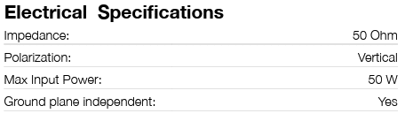
You can find the impedance value of Siretta’s antennas on each product datasheet, typically on the second page under “Electrical Specifications”. As standard, Siretta antennas have an impedance value of 50 ohms.
Understanding VSWR
One of the most widely used indicators of impedance matching quality is VSWR (Voltage Standing Wave Ratio). It describes the ratio of the maximum to minimum voltages in a standing wave pattern along a transmission line. In simpler terms, it quantifies how much of the transmitted signal is reflected due to impedance mismatch.
Key points about VSWR:
- A VSWR of 1:1 indicates perfect matching – no reflected signal.
- A VSWR of 2:1 is acceptable in many practical systems.
- A VSWR greater than 3:1 suggests significant mismatch and potential problems.
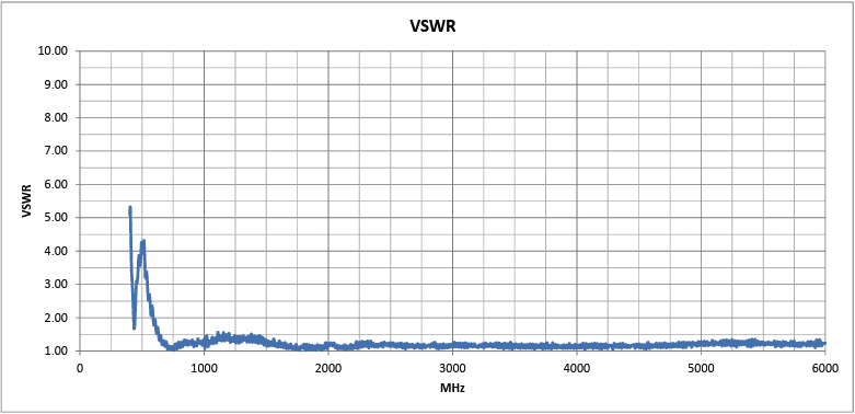
VSWR also varies across frequency. This is why you will find VSWR represented as a graph across the frequency in Siretta’s antenna datasheets.
How is Impedance Matching Measured?
To assess and correct impedance mismatches, engineers use a range of tools and techniques. These include:
- Vector Network Analysers (VNAs): These measure S-parameters across frequencies and can calculate impedance, reflection coefficients, and VSWR. VNAs are the gold standard for RF testing.
- Impedance Analysers: These are used for precise impedance measurements, particularly at lower frequencies or in component-level analysis.
- SWR Meters: Simpler than VNAs, SWR meters measure forwards and reflected power to determine VSWR directly.
- Smith Charts: A graphical tool used to plot complex impedance and guide the design of matching networks. Smith charts allow engineers to visualise how impedance changes across a transmission line or with frequency.
Maximise Power Efficiency with Impedance Matching
Impedance matching is essential for maximising power efficiency, minimising signal distortion, and protecting RF components. Understanding how it works – and how to measure it using tools like VNAs and VSWR – can greatly enhance the performance of any wireless or high-frequency system. While it may seem like a purely theoretical concept, the effects of poor impedance matching are very real and can undermine an otherwise well-designed system.

How to Select the Right Antenna for Your Application


How Environmental Considerations Affect Antenna Selection

Antenna Applications

Antenna Types Explained: Mounting Styles and Applications

Understanding Key Antenna Parameters


Understanding Antenna Radiation Patterns

Exploring IoT in Digital Twins & Building Information Modelling (BIM)

Waste and Fuel Management in Construction with IoT

Predictive Maintenance and Remote Machine Management in Construction Using IoT

Tool & Equipment Tracking in Construction Using IoT