

When learning about antennas, one of the most essential concepts to grasp is the radiation pattern. Without understanding this concept, it’s difficult to properly evaluate an antenna’s performance or determine whether it’s suitable for a specific application. Radiation patterns offer a visual and analytical way to understand where an antenna sends or receives most of its energy.
In this post, we’ll explore what radiation patterns are, why they are important, the different types, and how to read and interpret them effectively. This knowledge is crucial whether you’re designing wireless systems, installing antennas, or simply curious about how antennas function.
What is a Radiation Pattern?
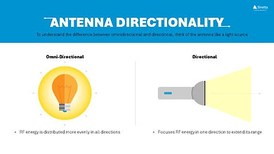
A radiation pattern is a graphical representation of the relative strength of the electromagnetic waves that an antenna radiates or receives in different directions. In simpler terms, it maps out how an antenna “focuses” its energy in space.
Radiation patterns provide insight into the areas where an antenna performs well and areas where its signal is weaker or absent. They are typically expressed in either two-dimensional or three-dimensional plots, showing how the power varies with the direction around the antenna.
Why Are Radiation Patterns Important?
Radiation patterns are not just theoretical tools; they play a practical role in antenna design and deployment. Engineers and system designers rely on them to optimise network performance and ensure efficient use of resources.
Some of the key reasons radiation patterns are important include:
- Helping select the right type of antenna for a given application.
- Allowing engineers to optimise signal coverage, ensuring strong connections where needed.
- Minimising interference with other systems by directing energy away from sensitive areas.
- Complying with regulatory requirements regarding signal direction and power limits.
By studying an antenna’s radiation pattern, you can effectively predict its behaviour in real-world conditions.
Types of Radiation Patterns
Radiation patterns come in several distinct types, based on how the antenna distributes energy.

The isotropic radiation pattern is a theoretical reference. It represents an idealised antenna that radiates equally in all directions, forming a perfect sphere of radiation around the antenna. While no real antenna behaves this way, isotropic radiation serves as a baseline for measuring and comparing the performance of practical antennas.
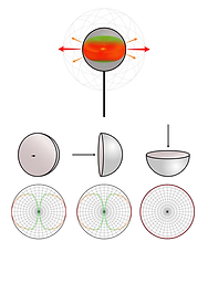
The omni-directional radiation pattern is common in many practical antennas. This pattern radiates energy equally in all directions along a horizontal plane, such as the ground. Visually, it resembles a doughnut shape, with the antenna at the centre. Omnidirectional antennas are typically used in applications like Wi-Fi routers, mobile base stations, and broadcast antennas where broad, uniform coverage is desired.
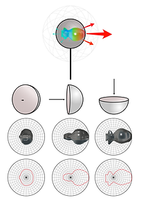
In contrast, the directional radiation pattern focuses energy in a specific direction. This creates a strong beam of energy pointing towards a target area, often with minimal radiation elsewhere. Directional antennas, such as satellite dishes and Yagi antennas, are widely used for point-to-point communication, where maximising signal strength in one direction is critical.
How to Interpret Radiation Patterns
Interpreting radiation patterns involves analysing the graphical representation of an antenna’s performance. These patterns are most often presented in polar plots, showing the signal strength relative to direction.

Key features of radiation patterns include the main lobe, which represents the direction of strongest radiation. Surrounding the main lobe, there may be side lobes – smaller areas of radiation in other directions. In some cases, deep dips known as nulls appear, indicating areas with minimal or no radiation.

The main lobe shows where the antenna is most effective, while side lobes and nulls can impact system performance, especially in environments where interference is a concern.
The Role of Logarithmic Scales in Radiation Patterns
Radiation patterns are often plotted using a logarithmic scale, specifically in units of decibels (dB). This is necessary because antennas can have significant variations in signal strength across different directions – sometimes by factors of hundreds or thousands.
Using a logarithmic scale compresses these large variations, making it easier to visualise both strong and weak areas of radiation within the same plot. In these graphs, the peak signal strength is typically set at 0 dB, and all other directions are shown relative to that maximum value.
This approach allows engineers to quickly assess details such as beamwidth (the angular width of the main lobe), sidelobe levels, and null depths.
Radiation Patterns in Orthogonal Planes
To gain a complete understanding of an antenna’s behaviour, radiation patterns are usually analysed in two key orthogonal planes.

The azimuth plane, also known as the horizontal plane, provides a top-down view of how the antenna radiates energy around itself at a constant elevation angle, usually aligned with the ground. This plane is particularly important for systems that require wide horizontal coverage, such as cellular base stations or broadcast towers.
The elevation plane, also called the vertical plane, shows how the antenna radiates energy at different elevation angles from a side view. This plane is crucial in applications like satellite communication or radar, where vertical coverage and tilt angles are significant factors.
By studying radiation patterns in both the azimuth and elevation planes, engineers can fully evaluate an antenna’s coverage characteristics and adjust installations to optimise performance.
Understanding Antenna Behaviour with Radiation Patterns
Radiation patterns are fundamental tools for understanding antenna behaviour. They provide critical insights into how an antenna radiates or receives energy, allowing engineers and designers to optimise performance for a wide range of applications.
By learning to interpret these patterns – including recognising main lobes, side lobes, and nulls, understanding logarithmic scaling, and analysing orthogonal planes – you’ll gain a deeper understanding of antenna performance and be better equipped to design, select, and deploy antennas effectively.

How to Select the Right Antenna for Your Application


How Environmental Considerations Affect Antenna Selection

Antenna Applications

A Guide to Impedance Matching

Antenna Types Explained: Mounting Styles and Applications

Understanding Key Antenna Parameters


Exploring IoT in Digital Twins & Building Information Modelling (BIM)

Waste and Fuel Management in Construction with IoT

Predictive Maintenance and Remote Machine Management in Construction Using IoT

Tool & Equipment Tracking in Construction Using IoT